Introduction
There’s a moment in almost every renovation or retrofit project when someone asks, “Are we sure this drawing matches what’s actually on site?”
It’s usually not a dramatic moment. It comes up in a coordination call or during a late-night review of a marked-up plan. But it points to a very real problem. Most buildings change over time, and the drawings don’t always keep up.
This is where the move from Scan to 3D Revit Model starts to earn its place. Not as a flashy digital upgrade, but as a practical way to reconnect floor plans, sections, and elevations with the reality of the building.
Why 2D Drawings Still Matter in a 3D Workflow
Even on projects built around BIM, 2D drawings are still the working language for many teams. Floor plans get printed. Sections get reviewed in meetings. Elevations get sent for approvals.
The difference today is where those drawings come from.
When floor plans, sections, and elevations are generated from a scan-based Revit model, they’re no longer just interpretations of old files. They’re views cut directly from a model that reflects current site conditions.
That shift changes how much trust teams place in the drawings.
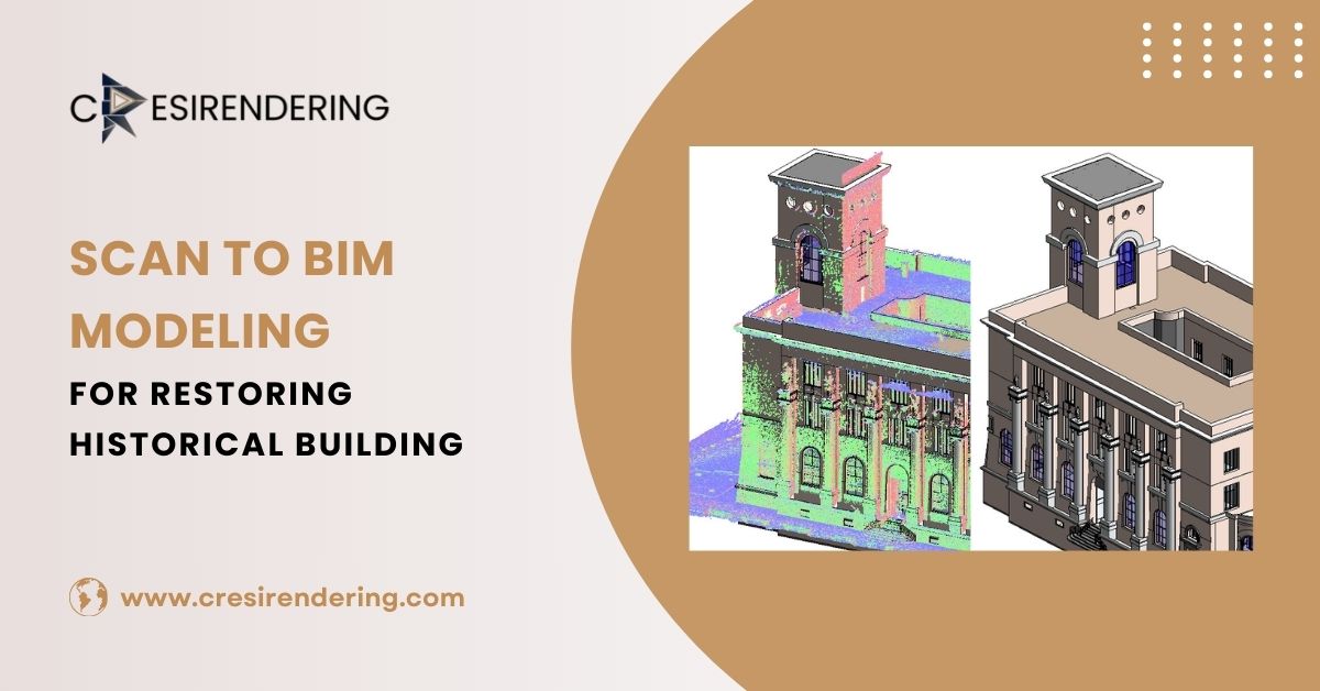
What “Scan to 3D Revit Model” Actually Means
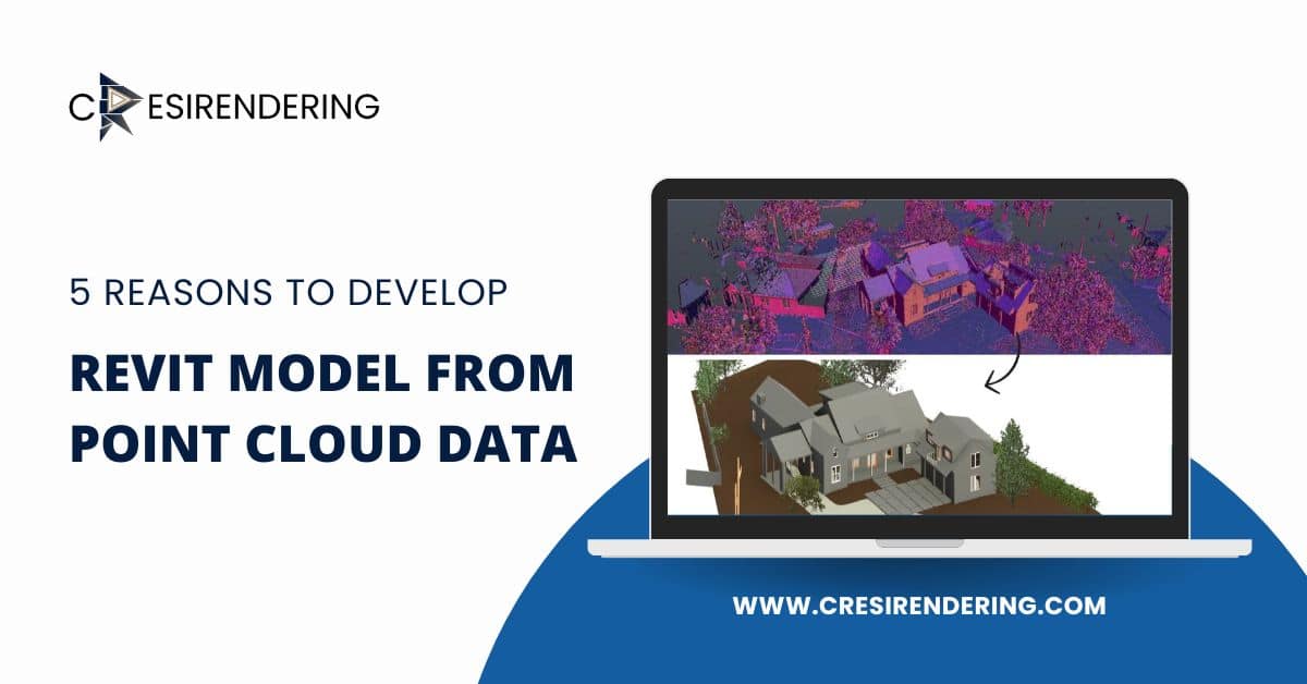
At a basic level, the process starts with laser scanning. Scanners capture millions of points that describe surfaces like walls, floors, columns, beams, and visible services. This forms a point cloud, which is a dense, three-dimensional record of the space.
On its own, a point cloud is great for reference, but it’s not something you can easily design from.
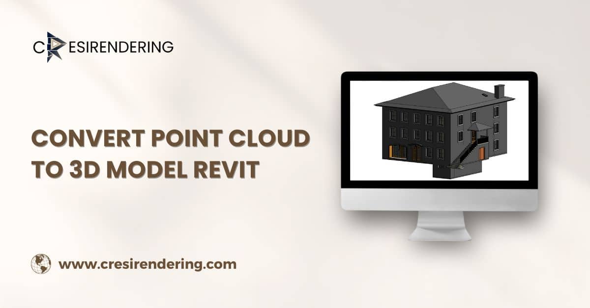
Turning that data into a 3D Revit model means rebuilding the building digitally. Walls become Revit elements. Floors gain thickness and structure. Openings, levels, and grids are defined. Major MEP and structural components are modeled in relation to the architecture.
Once that’s done, floor plans, sections, and elevations can be generated directly from the model instead of being drafted separately.
How Floor Plans Benefit from Scan-Based Modeling
Traditional floor plans often rely on legacy drawings or manual measurements. In buildings that have been modified over time, this can lead to small but important discrepancies.
A scan-based Revit model helps:
- Confirm wall locations and thicknesses
- Capture irregular geometry in older buildings
- Align rooms, corridors, and openings accurately
When a plan is cut from the model, it reflects what’s actually there, not what someone believes should be there.
This is especially useful for interior fit-outs, space planning, and MEP coordination, where inches can matter.
Sections That Explain the Building, Not Just Slice It
Sections are where a lot of coordination problems first show up. Ceiling heights, slab edges, structural transitions, and service routes all compete in the same vertical space.
With a scan-based model, sections become a tool for discovery rather than just documentation.
Teams can:
- Review clearances above ceilings
- Check how ducts and pipes pass through structure
- Understand floor-to-floor relationships in multi-level spaces
Because the model is built from real conditions, these sections tend to answer questions instead of raising new ones.
Elevations That Reflect Real Geometry
Elevations are often the first thing clients and planners look at. They care about proportions, alignment, and how the building sits in its context.
In renovation projects, facades and interior elevations can be tricky. Walls aren’t always straight. Openings aren’t always evenly spaced.
Scan-based Revit models help capture those realities. The elevations generated from them show true alignment and spacing, which supports both design decisions and approval processes.
The Workflow Behind Scan to 3d Model
Scanning and Data Capture
The process usually starts on site, with scanners placed strategically to cover key areas. Overlapping scans help ensure continuity, especially in complex or cluttered spaces.
Care is taken to capture not just main rooms, but also service areas, shafts, and transitions between spaces, the places where coordination issues often hide.
Point Cloud Processing
Once scanning is complete, the data is registered and cleaned. Temporary objects, noise, and misalignments are reduced. The goal is to create a clear, stable reference that can be used for modeling.
Revit Modeling
This is where judgment comes in. Not every point in the cloud becomes a modeled element. The focus is on building components that affect design, coordination, and construction.
Architectural elements, structure, and major MEP systems are modeled to the required level of detail, based on how the model will be used.
Why Level of Detail Matters?
A model built for documentation doesn’t need the same detail as a model built for fabrication or facility management.
Most projects define a target LOD:
- Lower detail for planning and layout
- Higher detail for coordination and construction
- Highest detail for long-term asset management
Keeping this clear prevents over-modeling, which can slow teams down without adding real value.
How Scan to 3d model support Coordination Across Disciplines?
When floor plans, sections, and elevations all come from a single model, architects, engineers, and contractors are looking at the same information.
Changes in one view reflect in the others. That consistency reduces miscommunication and helps teams spot conflicts earlier.
This is particularly valuable in MEP coordination, where vertical and horizontal space is limited and systems interact closely.
Where This Approach Adds the Most Value
- Renovations and retrofits, where existing conditions are uncertain
- Commercial interiors, where layout precision affects services and finishes
- Healthcare and institutional buildings, where clearances and compliance matter
- Heritage projects, where geometry often deviates from standard assumptions
In these settings, scan-based models often become the backbone of the documentation set.
Common Challenges and How Teams Handle Them
Incomplete or Obstructed Scan Data
Furniture, equipment, and access restrictions can hide parts of the building. Experienced teams note these gaps and avoid making assumptions without verification.
Large File Sizes
Models can become heavy. Breaking them into logical zones or worksets helps keep performance manageable.
Interpreting Irregular Geometry
Older buildings rarely follow perfect grids. Careful modeling helps capture these quirks without turning the model into an unmanageable level of detail.
Also read: How Architects Use 3D Architectural Visualization Walkthroughs to Improve Client Approvals
Conclusion
Creating floor plans, sections, and elevations from a scan-based 3D Revit model brings drawings closer to reality. Instead of relying on outdated files or assumptions, teams work from a digital version of the actual state.
For architects, engineers, and construction teams, this often means fewer surprises, clearer coordination, and more confidence in the drawings that guide decisions on site.
In projects where existing conditions matter, which is most of them, the connection between the real building and the digital model can make a quiet but lasting difference.